
SUMMARY
1. Introduction
2. Bill of Materials
3. Block Diagram
4. Schematics/CAD DESIGN
5. Assembly
6. Final Thoughts/ Improvements
7. Download Original Files
INTRODUCTION
Arduino and the implementation of GRBL has allow for amazing things to be created. One of those things are low cost CNC machines that enable us to create anything we want.
I bought myself a low cost CNC engraver from amazon and after modifying it, it has been one of my best investments because as en electrical engineer I can create PCB boards to test my designs here at home and verify before getting them sent out. One problem I usually have is that I use my laptop to run the gcode software and my laptop is really big and sometimes a hassle to keep on my desk.
My solution was to create this project and make a standalone CNC machine controller to run the gcode software in a compact package. I tried fiddling around with using a raspberry pi 2 as my main PC but I’m still a beginner with raspberry pi’s and I had issues getting the settings right. My next option was to use a windows based machine and luckily I found just the solution.
In this tutorial I will explain how I put this together and what improvements could be made.
BILL OF MATERIALS
| Component | Quantity | Link |
| Windows computer stick | 1 | Amazon |
| Wireless keyboard/mouse | 1 | Amazon |
| DIY HDMI male adapter angled | 1 | Adafruit |
| DIY HDMI female adapter | 1 | Adafruit |
| DIY HDMI Ribbon cable 20cm | 1 | Adafruit |
| 3.5 inch Screen | 1 | Amazon |
| Left angled micro usb cable | 1 | Amazon |
| Top angled usb 3.0 extension | 1 | Amazon |
| USB Board | ||
| USB Female Connector | 2 | Sparkfun |
| 5VWM TVS Diode | 1 | Digikey |
| 0.1uF 50V X7R 1206 | 1 | Digikey |
| 1uF 25V X7R 0805 | 1 | Digikey |
| 10uF 16V X5R 0805 | 1 | Digikey |
| 100 OHM 0.1% 1/8W 0805 | 2 | Digikey |
| TERM BLOCK 5MM 2POS | 2 | Digikey |
BLOCK DIAGRAM
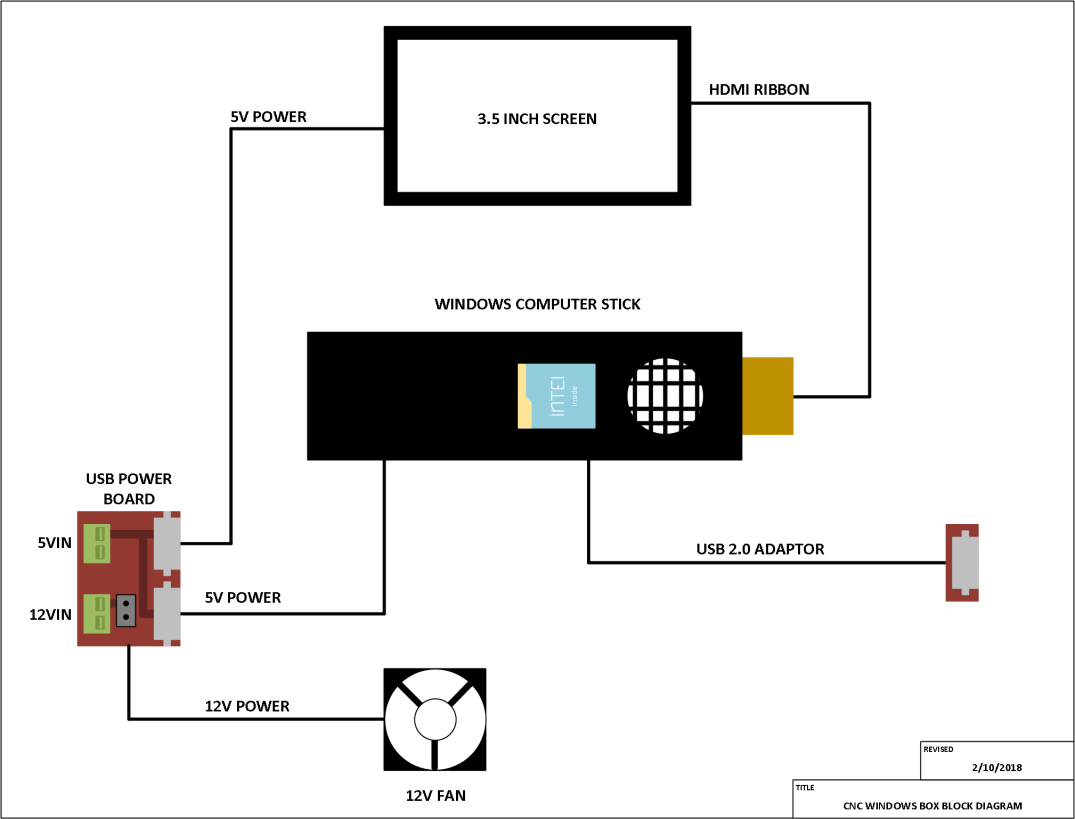
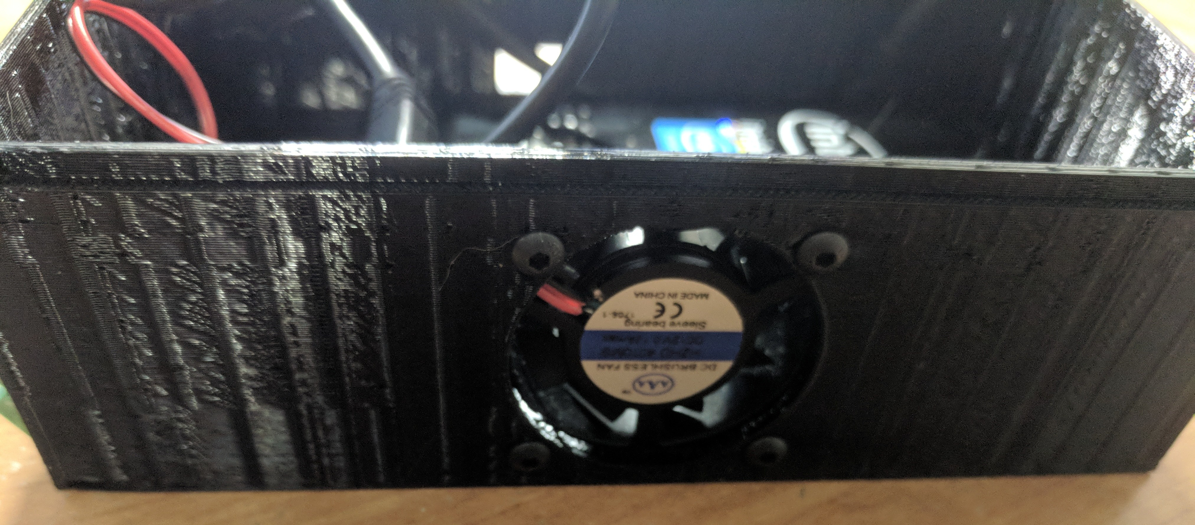
Here is the block diagram for how this project is wired. With the exception of the enclosure itself and the usb power board, everything was bought ready to go. I’ve added a fan as a just in case because the computer stick does generate some heat so the fan will prevent the system from over heating but so far it does not seem to be an issue with heat and therefore is an option.
The 5V and 12V supply are coming from my 24V power supply that powers my Arduino GRBL shield. What I did was use two step down converters 1) For 5V step down and 2) For 12V step down. I realized this might not be idle but it is my first revision of this project.
SCHEMATICS/ CAD DESIGN
The only schematics I have is for the USB power board and I created that using Kicad. The board was basic, since both the screen and the windows computer stick ran on 5V via micro USB, I needed to distribute power from one source into two loads. To add some safety, I did add a TVS 5VWM diode to prevent over voltage spikes from destroying the devices along with some filtering capacitors.
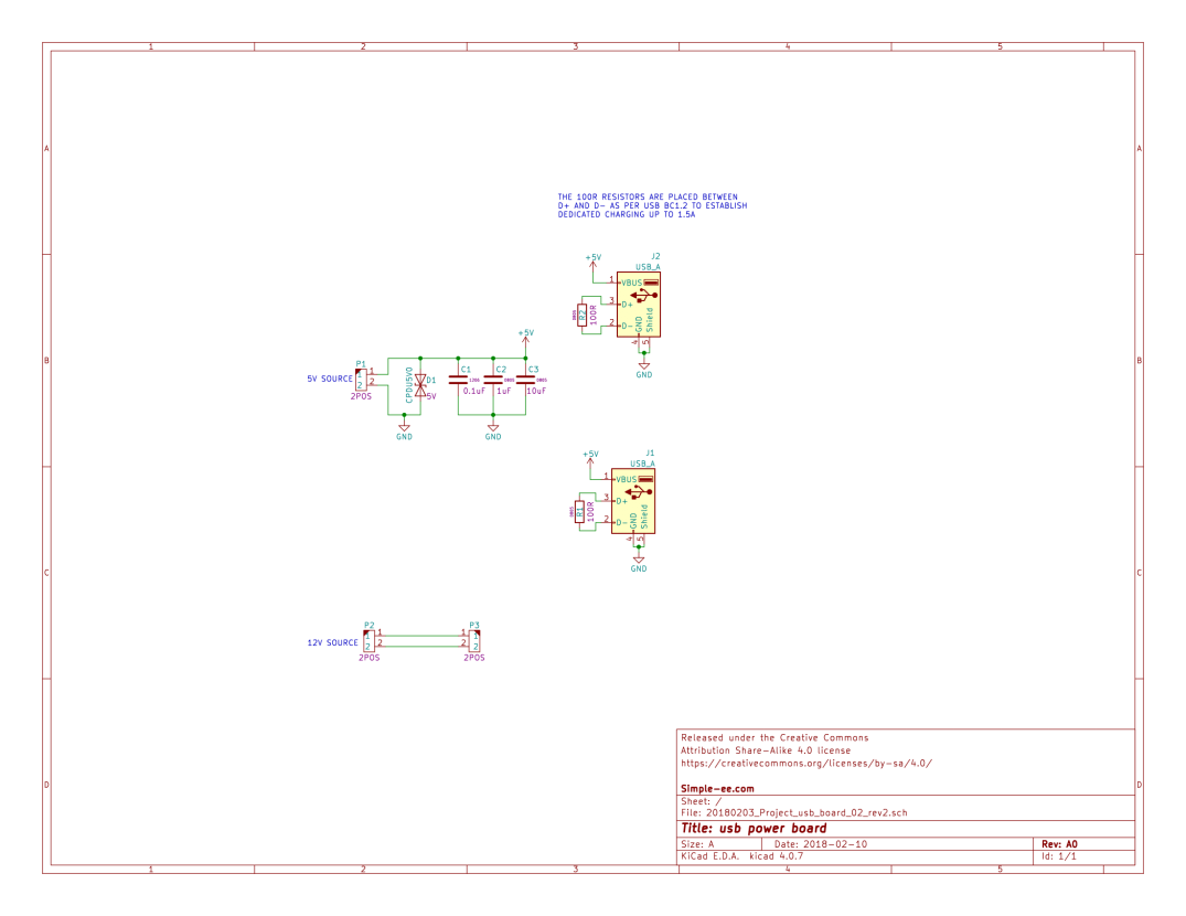
If its a little blurry don’t worry because all original files will be included in a download link at the end.
Now for the enclosure, I designed it using Fusion 360. Honestly, I am not a Mechanical engineer/Designer so this was my first attempt at designing something in a CAD software. Mine you its really just a box but Fusion 360 makes it really easy to design for someone who had no prior experience.
I designed this in two pieces:
- The bottom portion of the enclosure:
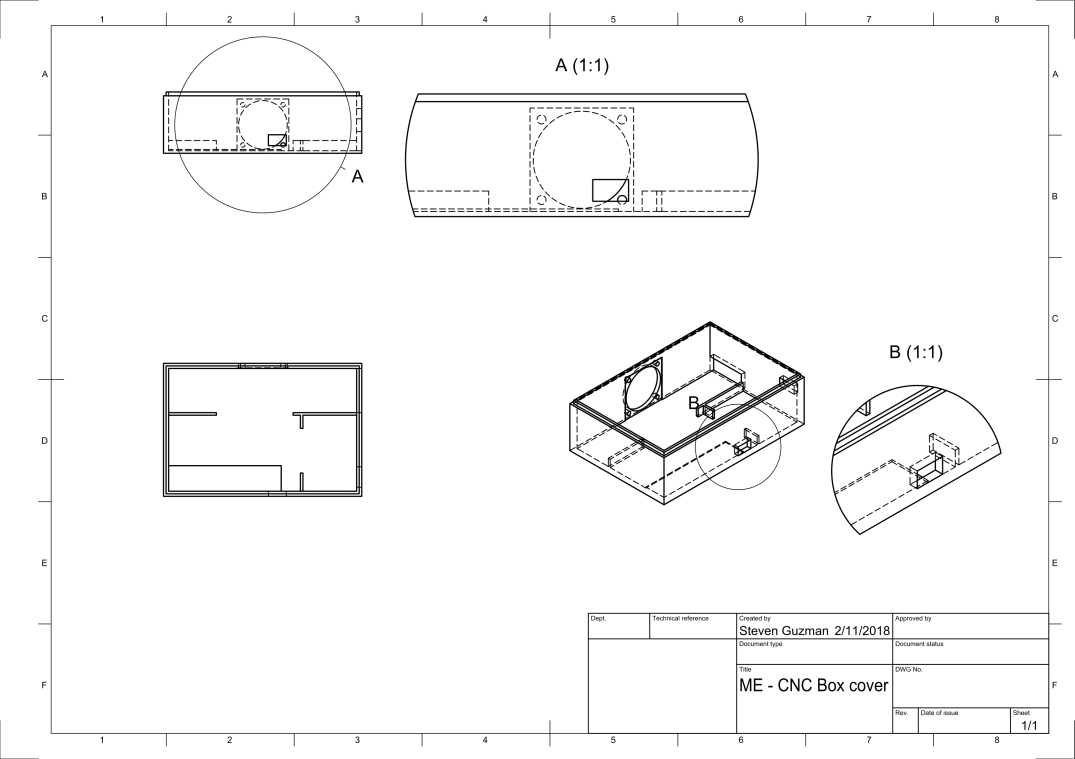
- The Lid for the enclosure:
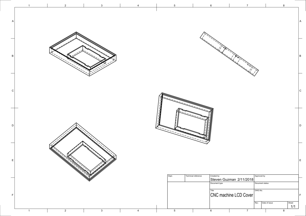
For material used for making this enclosure, I used my Maker Select V2 3D printer with PETG filament for the temperature resistance and flexibility.
I will include the STL files so you guys can 3D print this yourself.
ASSEMBLY
Now for the fun part, putting this thing together and hoping everything works without the magic white smoke lol jk. This was actually very easy to put together though there were a couple of design hick ups.


Since I wanted to get the print out as fast as possible, I sacrificed quality of the print which is why it looks the way it does but its very function.
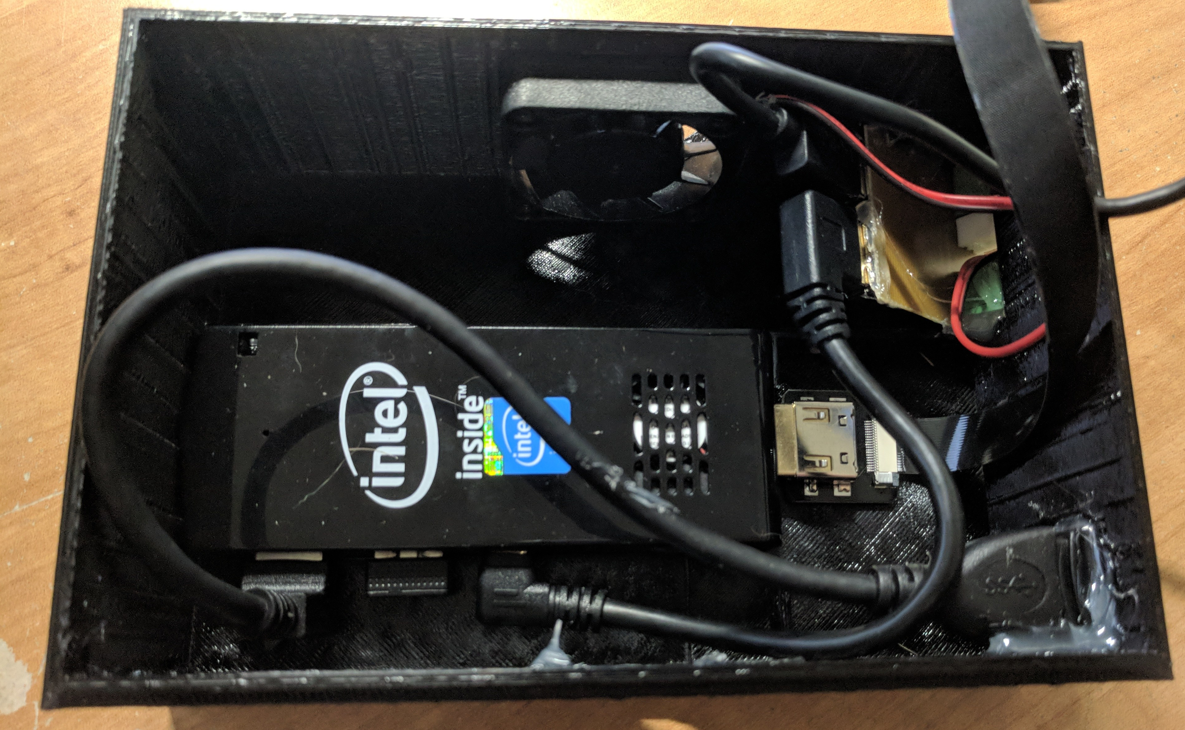
As I mentioned I did have some design issues after I was putting this thing together. If you look at image 3, you can see that the usb power board is tilted up and thats because I placed the cooling fan to close. The board was able to fit but I could not connect anything because the fan was blocking the connectors.
I decided to use hot glue to hold everything down because it wouldn’t be a DIY project if hot glue wasn’t involved.
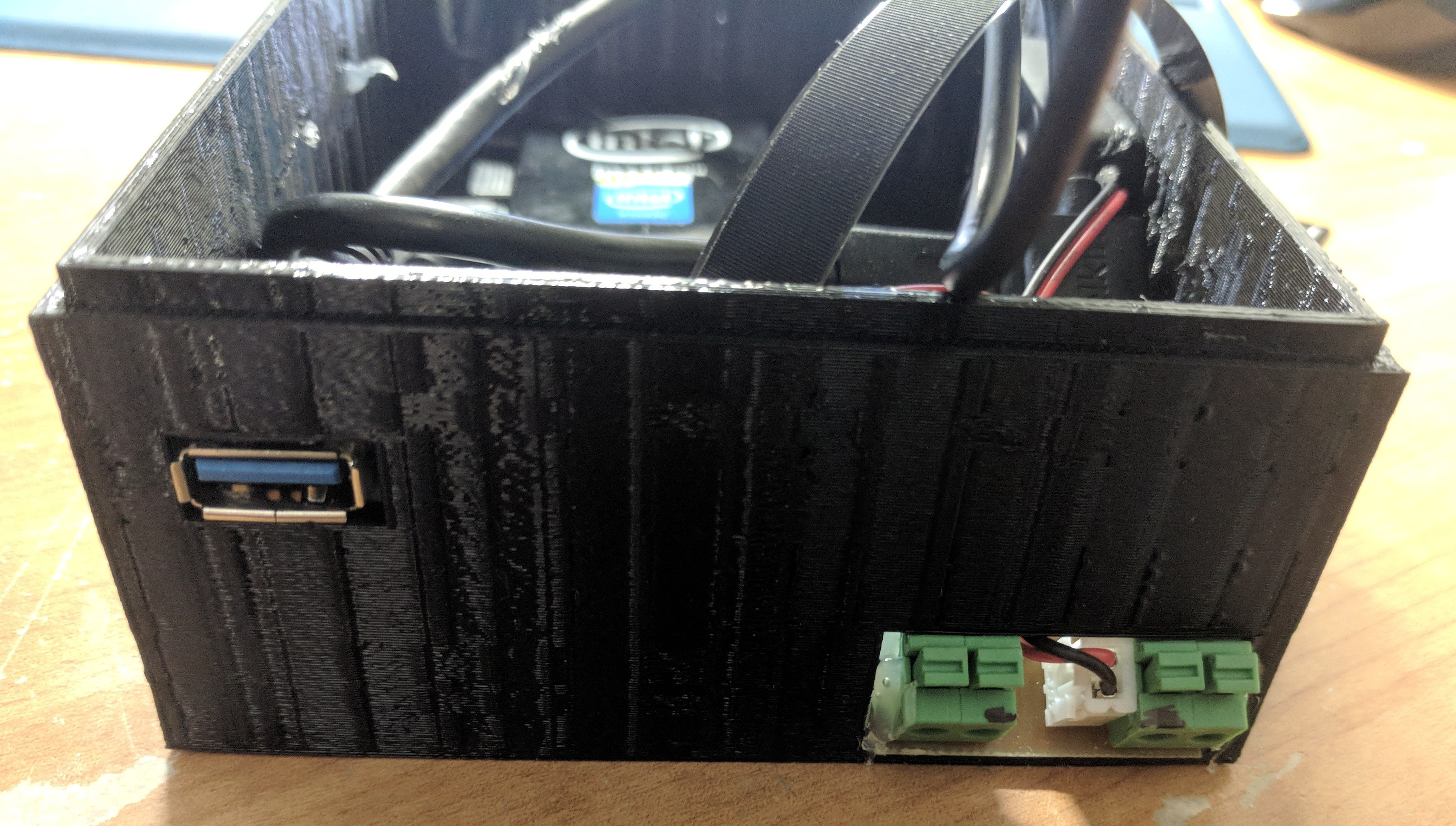
In image 4, you can see I used some basic terminal block connectors to attach my 5V and 12V supply. You can also see the USB port to connect the arduino grbl controller board.
FINAL THOUGHTS/IMPROVEMENTS


Overall I enjoyed putting this project together. It’s made my project efficiency increase dramatically because I don’t have to take it out and set it up every time I want to make a board.
With anything we do, there’s always room for improvements. In a future version of this project I plan to improve the way I connect my external 5V and 12V supply instead of using the terminal blocks. I might possibly use some type of molex connector that can easily detach. To reduce the amount of external connectors, I could switch out the 12V fan with a 5V fan and run it with only one step down converter. I’m going to also move the fan placement so that I do not have to angle the usb power board.
DOWNLOAD ORIGINAL FILES
Thank you for visiting and I hope you enjoyed this project.
Please leave a comment and let me know about your thoughts, improvements or any issues you see with this post. All comments are welcomed 🙂
