

Introduction
Lets build a WiFi temperature data logger!! The reason this project came to mind was because I needed to monitor the temperature of an outside enclosure box that will eventually house a couple of lithium ion batteries. Can’t have the box get too hot or else we will end up having a nice backyard campfire.
This temperature data logger consist of three sections:
- The WiFi web server
- The temperature sensor
- The sleep controller
Lets get into the project now 🙂
Schematics, PCB, Arduino Libraries can be downloaded Here
Bill of Materials
- x1 ESP8266 – Link
- x1 Barometric (BMP180) – Link
- x1 Atmega328P-PU – Link
- x1 FTDI to Serial Converter – Link
- x1 2N7002 – Link
- x1 DMG2305UX-7 – Link
- x7 10k Resistor 1206 – Link
- x3 0.1uF Capacitor 1206 – Link
- Female Headers – Link
- x1 28 pin DIP Socket – Link
- x1 PCB Terminal block – Link
- x1 3.3V Boost Converter – Link
Hardware/Schematic/Assembly
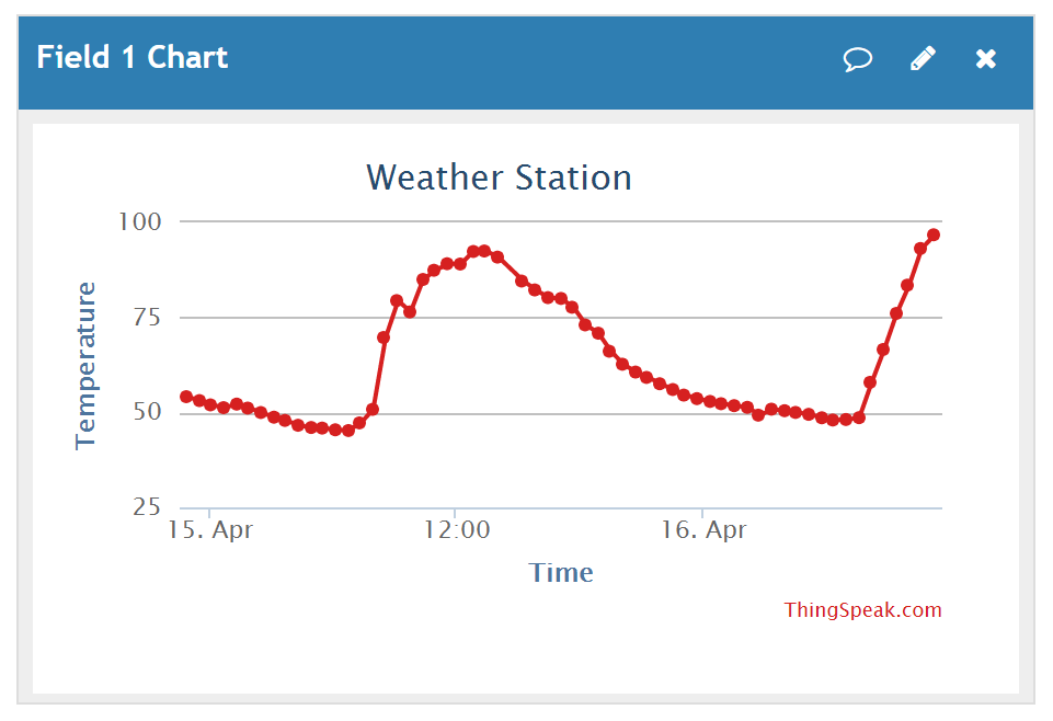
I’ve designed this project to consist of two microcontrollers. Its not the most efficient way of doing it but it is effective. The heart of this project is the ESP8266-ESP01 IC. It will take in the data from the BMP180 sensor over I2C and send the data over to a web hosting site Thingspeak.com
Schematic:
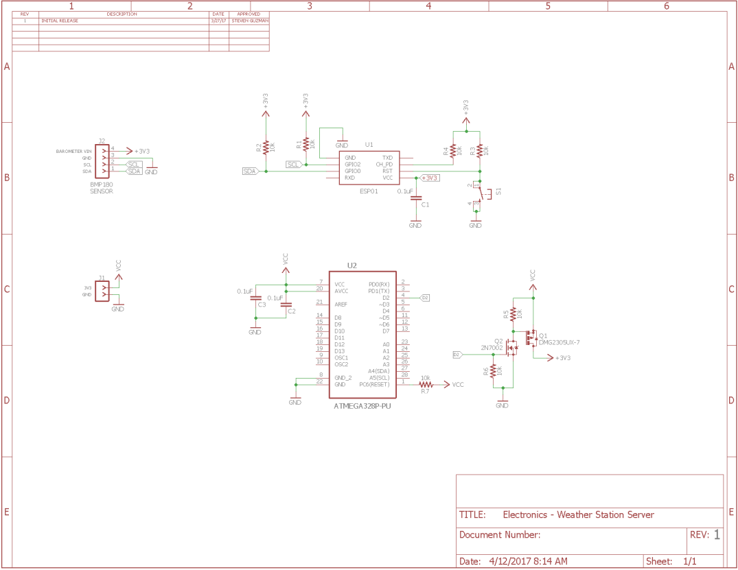
The schematic is not that all complicated but it is very effective at trying to save as much battery as possible and deliver my data for viewing purposes.
In order to have this be powered by 2x AA batteries and last longer then a couple of days or weeks, I needed a couple of things to make this possible which is where the second microcontroller comes into play.
First, we need to make sure we have a stable power supply that can provide up to at least 0.3A and have a minimum quiescent current in the low uA range.
Thingspeak.com
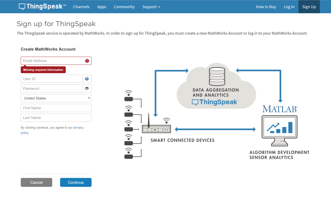
Before we get started into writing the code on the ESP8266 we need to set up an account at thingspeak.

Click on the signup and fill out the information:
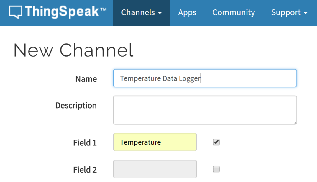
Click on new channel:

The most important information to fill out is the fields, in our case we will fill out field 1 and type in temperature. The name could be any name you want, for this purpose we will write Temperature Data Logger. Once finish, scroll down and click save.
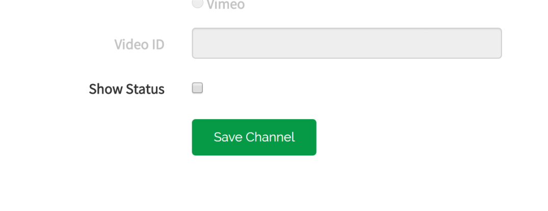
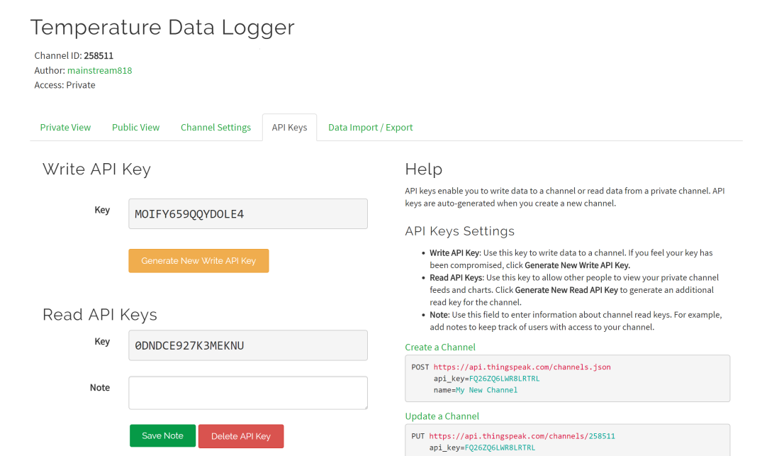
The final piece of information we need is the API key, for this just click on the API Keys button and copy the Write API Key.
Now we can move on to the code.
Click here for step by step on installing the ESP8266 arduino addon.[3]
ESP8266 Code
//////////////////////////////////////////////////////////////////////////////////

// Name: Steven Guzman                                                          //

// Date: 4/4/2017                                                               //

// Description: Temperature webserver that will update every 30 minutes to      //

//              thinkspeak with data that shows the temperature of the inside   //

//              of the enclosure.                                               //

//////////////////////////////////////////////////////////////////////////////////

#include <ESP8266WiFi.h&>

#include <Wire.h>

#include <SFE_BMP180.h>

SFE_BMP180 pressure;

char status;

double t, tf;

// Replace with your channel's thingspeak API key

String apiKey = "";

// Enter your wifi information below

const char* ssid = "";

const char* password  = "";

const char* server = "api.thingspeak.com";

WiFiClient client;

void setup()

{

Serial.begin(115200);

delay(10);

// Pin 0 = SDA

// Pin 2 = SCL

Wire.begin(0,2);

WiFi.begin(ssid,password);

Serial.println();

Serial.println();

Serial.print("Connecting to ");

while (WiFi.status() != WL_CONNECTED)

{

delay(500);

Serial.print(".");

}

Serial.println("");

Serial.println("WiFi Connected");

// Initialize the sensor

if (pressure.begin())

{

Serial.println("BMP180 init success");

}

else

{

Serial.println("BMP180 init fail\n\n");

//while(1);

}

// Print the IP address

Serial.print("Use this URL to connect: ");

Serial.print("http://");

Serial.print(WiFi.localIP());

Serial.println("/");

}

void loop()

{

// This starts the BMP180 sensor and takes a reading

status = pressure.startTemperature();

if (status !=0)

{

delay(status);

status = pressure.getTemperature(t);

}

// Converts Celsius into Farenheid

tf = (9.0/5.0)*t+32.0,2;

if(client.connect(server,80))

{

char t_buffer[10];

// This will convert the double variable into a string

String temp=dtostrf(tf,0,5,t_buffer);

String postStr = apiKey;

postStr +="&field1=";

postStr += String(temp);

postStr +="\r\n\r\n";

client.print("POST /update HTTP/1.1\n");

client.print("Host: api.thingspeak.com\n");

client.print("Connection: close\n");

client.print("X-THINGSPEAKapiKey: "+apiKey+"\n");

client.print("Content-Type: application/x-www-form-urlencoded\n");

client.print("Content-Length: ");

client.print(postStr.length());

client.print("\n\n");

client.print(postStr);

Serial.print("Temperature: ");

Serial.println(t);

Serial.println((9.0/5.0)*t+32.0);

Serial.println(temp);

}

client.stop();

Serial.println("Waiting...");

delay(20000);

}
Arduino Code
///////////////////////////////////////////////////////////////////////////////////////////

/// Title:  Auto Garden Project                                                          //

/// Author: Steven Guzman                                                                //

/// Date:   4/6/17                                                                      //

/// Description: This project will automatically water a plant when the sensor reads low //

///              water levels in the soil.  If sensor reads low water, it will turn on   //

///              boost converter that controls the solenoid valve and then turn on the   //

///              solenoid valve control circuit to allow water to flow into the soil.    //

///////////////////////////////////////////////////////////////////////////////////////////

#include <LowPower.h>

int ESP1 = 2;          // Turns on sensor; set to low for battery consumption purposes (Active High)

void setup()

{

pinMode(ESP1,OUTPUT);     // Configure sensor control as output

digitalWrite(ESP1,LOW);   // Setup as low output

delay(100);

}

void loop()

{

digitalWrite(ESP1,HIGH);  // Turns on the ESP8266

delay(15000);             // 15 second delay

digitalWrite(ESP1,LOW);   // Turns off the ESP8266

// Loops the 8 second internal to extend the sleep state

// 15 = 2 minutes

// 37 = 5 minutes

// 75 = 10 minutes

// 112 = 15 minutes

// 255 = 30 minutes

for(int x = 0; x <= 255; x++)

{

LowPower.powerDown(SLEEP_8S,ADC_OFF,BOD_OFF);

}

}
Programming
ESP8266-ESP01
First things first, we will upload the code to the ESP8266-ESP01. This one is a little bit tricky but after awhile you’ll get the hang of it.
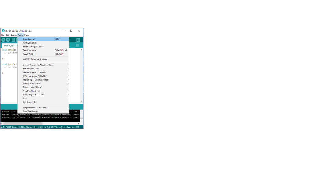
You need to make sure your settings are correct under the Arduino IDE.
See image below:
Here’s the wiring diagram for connecting the FTDI programmer to the ESP8266:
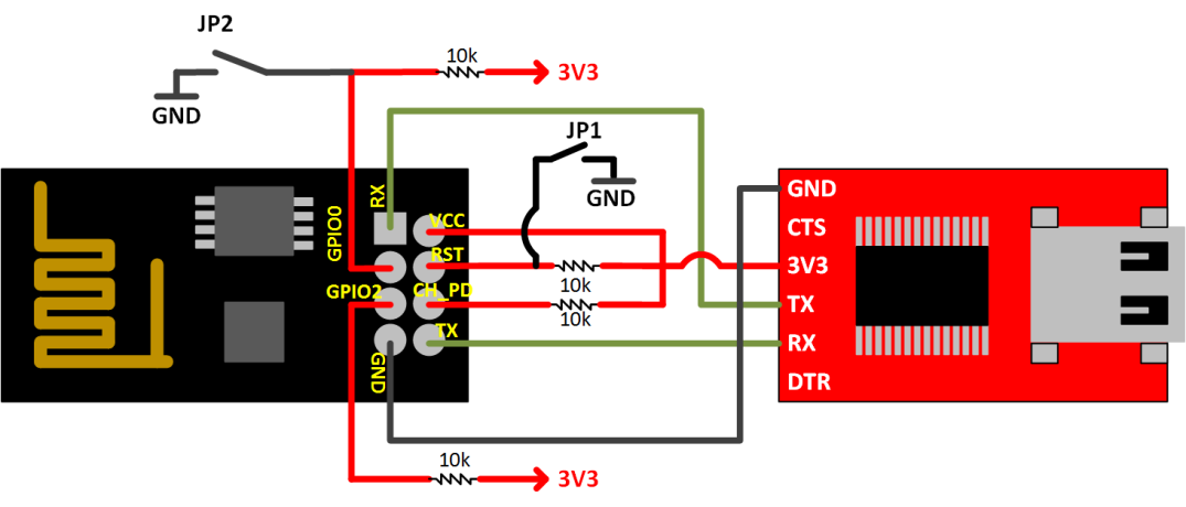
Now that your settings are correct, this is were it gets a little tricky to upload the code, you need to follow the steps below in order to upload correctly and successfully
Before hitting upload:
- Ground GPIO0 (hold down the push button JP2)
- Reset by pulling RST pin to ground (Press and release JP1 button)
- Once it restarts, hit the upload sketch icon
- When you see compiling sketch switch to uploading, then release the GPIO0 pin
- uploading should begin
ATMEGA328P-PU (ARDUINO LILYPAD)
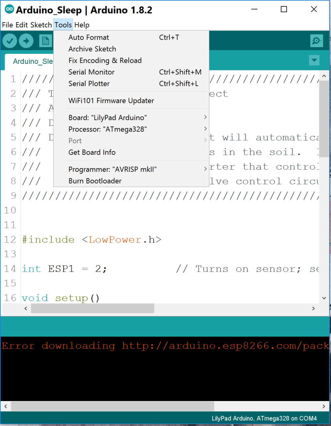
Next, we will upload the second code into the ATmega328 which has the lilypad bootloader installed ( Click HERE [2] for tutorial on flashing ATMEGA328P-PU with bootloader).
See image below for settings:
Final Thoughts and Future updates
And now the final product:


Its not the most elegant but I actually used my CNC machine to make these boards, in the future I might get them professionally made but for now its perfect for me.
Future Updates:
- Replace the ATMEGA328P-PU IC with a smaller ATTINY85 which can also be flashed with the Arduino bootloader
- Connect the Arduino to the I2C communication lines to expand its data logging capability
- Since this is running on 2x AA NiMH batteries, it would be great to monitor battery capacity. We can use one of the analog pins on the arduino to read the data and send it over I2C to the ESP8266
1. Arduinesp
