First I would like to say thank you in advance for visiting my site. My goal is to help anyone who loves to work with electronics.

TABLE OF CONTENTS
1. Introduction
2. Bill of Material
3. Block Diagram
4. Schematics
5. Arduino Uno sketch and upload
6. ESP8266 sketch and upload
7. Final thoughts
8. Download original files
INTRODUCTION
I don’t know about you guys but when it comes to closing my garage door I always seem to forget. Most of the time I don’t even notice until the night before I head to bed. I was getting tired of leaving it open so then I was inspired to create this project.
The garage door indicator project essentially sends you a text if the garage door is left open for more than 5 minutes. It uses an arduino, ESP8266, and IFTTT to remind me that I left it open.
Lets get started!
BILL OF MATERIAL
| Board | Part | Quantity | Link |
| Arduino Board | |||
| Arduino Pro Mini | 1 | Amazon | |
| ESP8266 Board | |||
| ESP8266 ESP01 | 1 | Amazon | |
| RC1206JR-0710KL | 4 | Digikey | |
| C1206C104K5RAC7867 | 2 | Digikey | |
| Boost Converter #1: Arduino Board | |||
| GRM21BR61E475MA12L | 1 | Digikey | |
| MCP1640T-I | 1 | Digikey | |
| GRM21BR61C106KE15K | 3 | Digikey | |
| RC0805JR-07560KL | 1 | Digikey | |
| TC33X-2-105E | 1 | Digikey | |
| MSS5131-103ML | 1 | Coilcraft | |
| Boost Converter #2: ESP8266 | |||
| AAT1217ICA-3.3-T1 | 1 | Digikey | |
| GRM21BR61E475MA12L | 1 | Digikey | |
| GRM21BR61C106KE15K | 3 | Digikey | |
| RC1206JR-071ML | 1 | Digikey | |
| MSS5131-472ML | 1 | Coilcraft | |
| Switch: ESP8266 Power | |||
| DMG2305UX | 2 | Digikey / Arrow | |
| 2N7002-7-F | 1 | Digikey | |
| RC1206JR-0751KL | 1 | Digikey | |
| RC1206JR-0710KL | 1 | Digikey |
BLOCK DIAGRAM
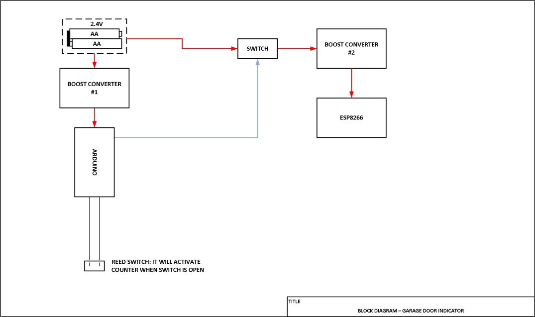
Here the block diagram gives you a general idea of how this is connected together. I’ve made this project very modular so upgrades and replacements are easy to do. I decided to go with two boost converters because the ESP8266 has a lot of noise issues that always messed with my arduino board and so separating the supplies and the controllers from each other did the trick.
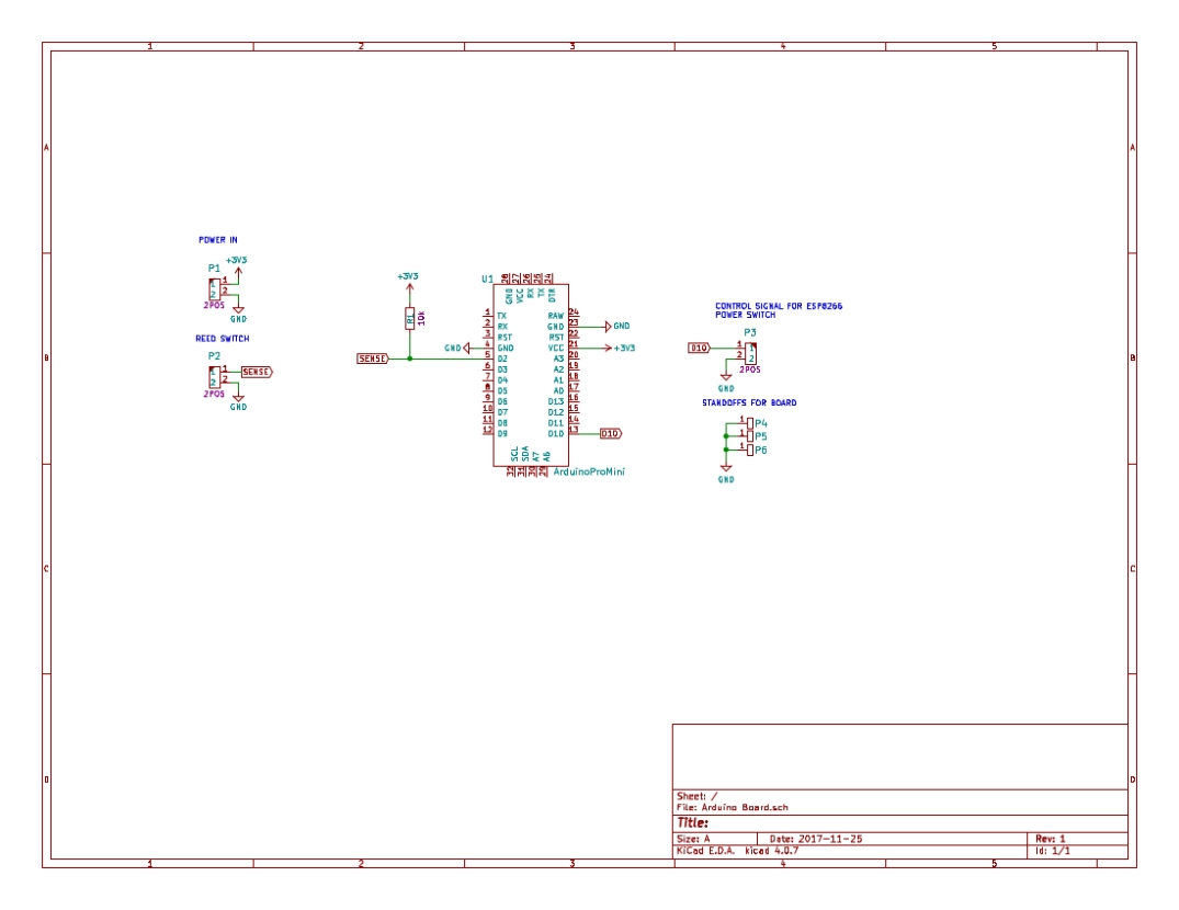
SCHEMATICS
Below I’ve listed all the schematics that are associated with this design. I’ve designed this project to be very modular because I CNC mill all the boards and it makes it a lot easier to work with.
If you click on the schematic images, i’ll take you to the pdf version that you can download.
Arduino nano board:
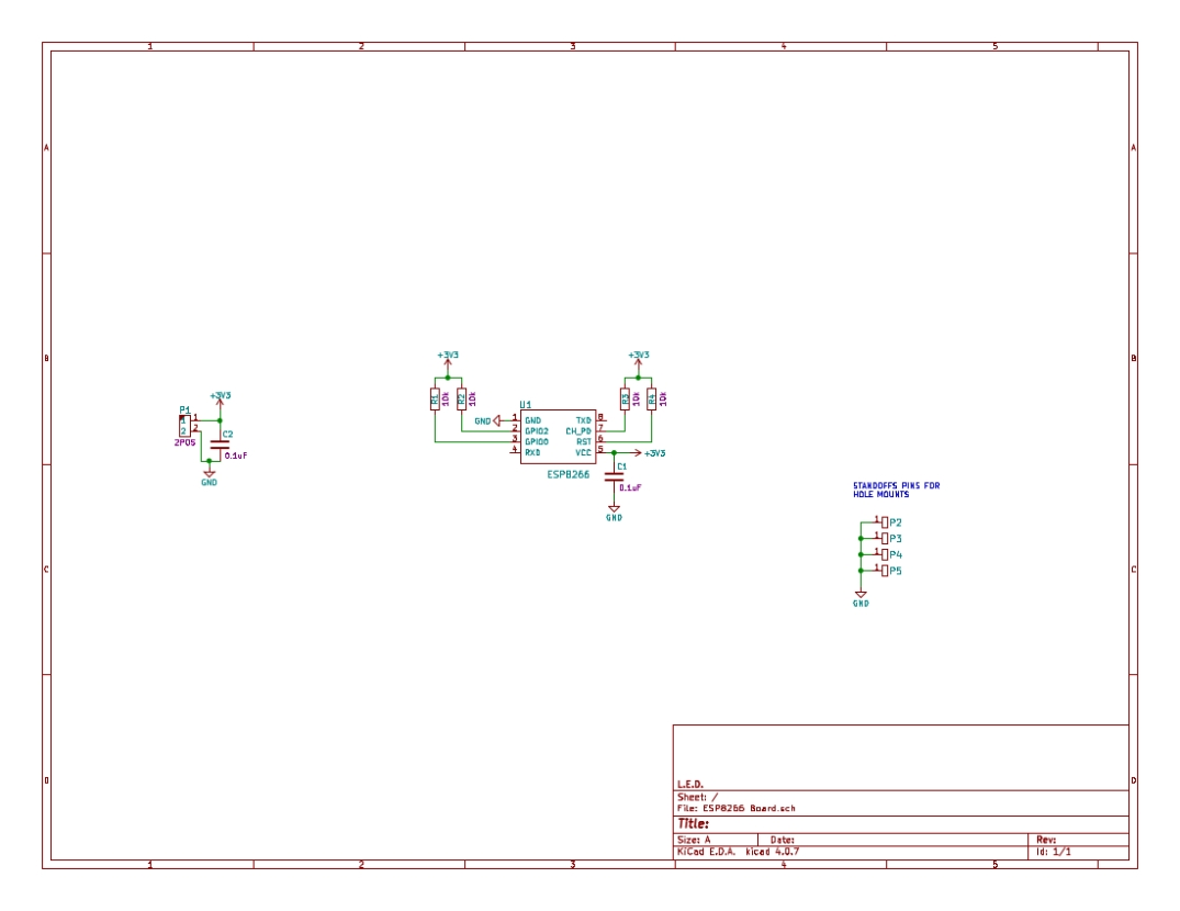
ESP8266 Board:
Boost Converter #1:
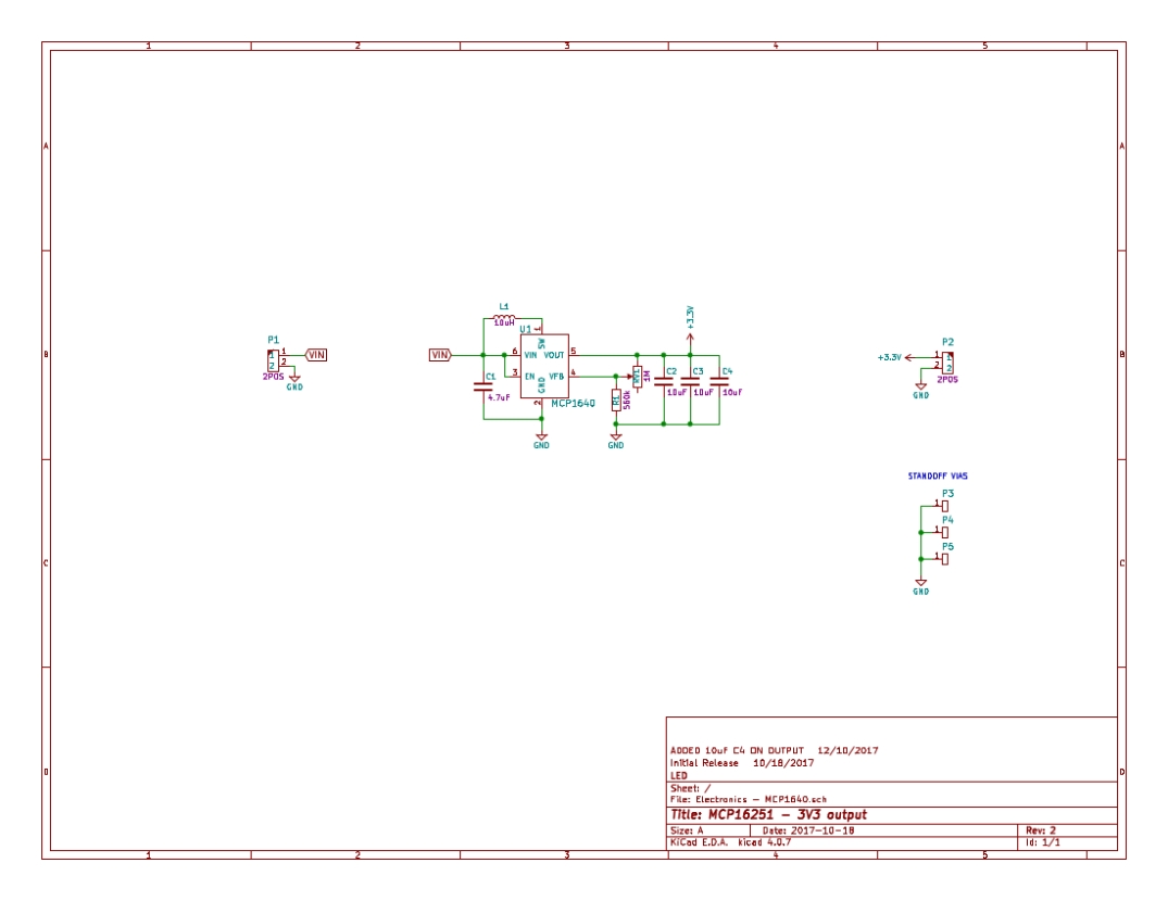
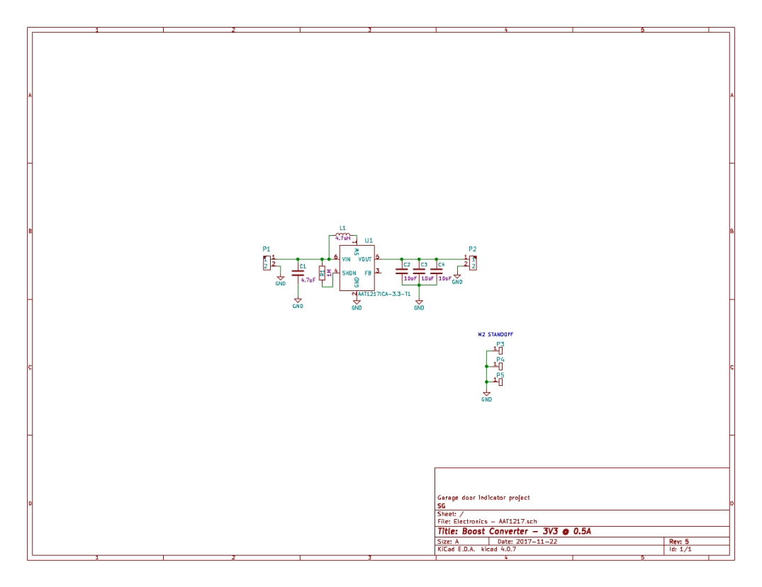
Boost Converter #2:
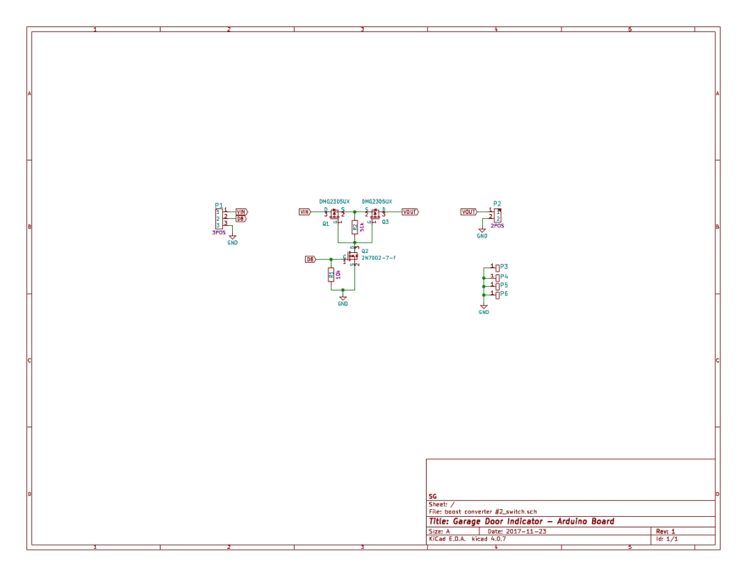
Switch: ESP8266 Power:
ARDUINO NANO SKETCH
Here is the arduino sketch used in the garage door project. Essential the arduino nano is used to first sense the status of the garage door and second to wake up the ESP8266.
The way this sketch is written is the arduino is put into an 8 second sleep state because thats the longest the watchdog timer will fire. This is then looped in that adds up to 5 minutes.
The reed switch is connected to the interrupt pin 2 on the nano and is used to wake up the arduino when the door is open. Then a counter will start counting and when 5 minutes are up that the door is left open, this will activate the switch that will turn on the ESP8266.
#include "LowPower.h"

int ESP8266 = 10;

int Open = 2;

int x = 0;

void setup()

{

  pinMode(ESP8266,OUTPUT);

  pinMode(Open,INPUT);

  digitalWrite(ESP8266,LOW);

  delay(500);

}

void loop()

{

  // put your main code here, to run repeatedly:

    // Low power sleep mode is used here to put the arduino

    // in an 8s sleep state

    LowPower.powerDown(SLEEP_8S,ADC_OFF,BOD_OFF);

    if (digitalRead(Open) == HIGH)

    {

      x = x + 1;

    }

    // Here is the value entered that will

    // set the time it takes for it to

    // wake up the ESP8266

    // 2 minutes = 15

    // 4 minutes = 30

    // 5 minutes = 39

    // 10 minutes = 80

    if ( x == 39)

    {

      digitalWrite(ESP8266, HIGH);

      delay(10000);

      digitalWrite(ESP8266,LOW);

      x = 0;

    }

    if (digitalRead(Open) == LOW)

    {

      x = 0;

    }

    delay(100);

}
All sketches and libraries will be attached in the links at the end of the post under download files
ESP8266 SKETCH AND UPLOAD
After the arduino nano is configured to wake up the ESP8266, the next thing we will do is load the sketch for the ESP8266.
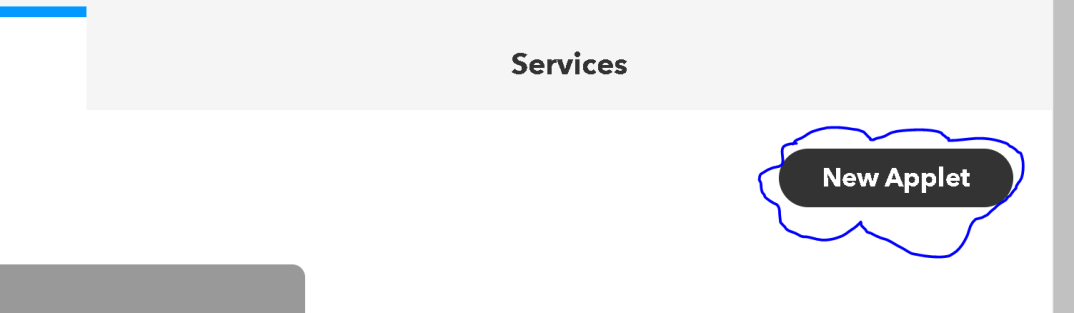
Now before we go into the sketch, we first need to setup an account with IFTTT.com. After that is done then we need to create a new applet.
Next, we click on If this:

Next, we search for webhooks service:
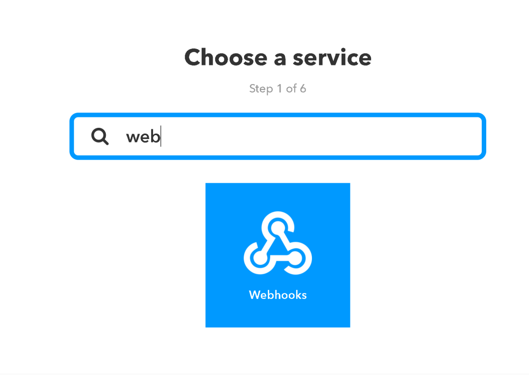
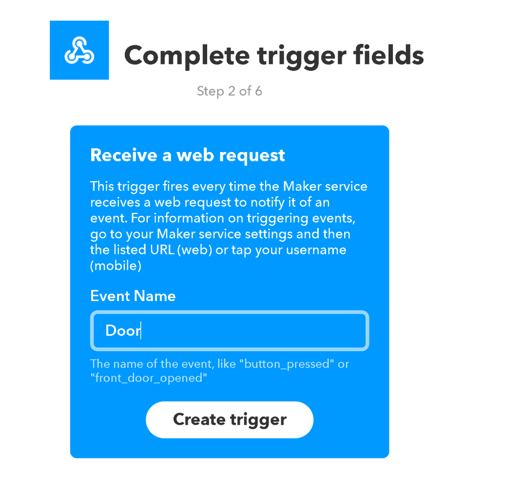
After that, we create the trigger. Here we enter “Door” as our trigger:
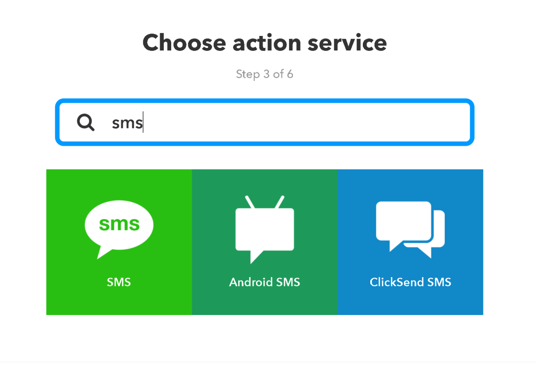
Now we need to create the action, in this case send a text when this is activated. We click on THAT now:

We search for SMS and click on the first one:
We now set the action, leave it as is and click on create:
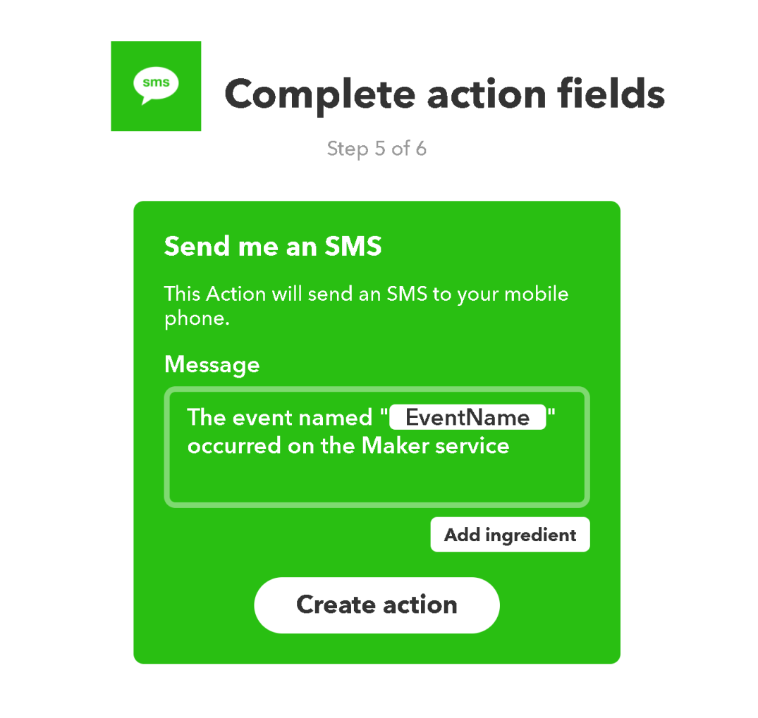
Then you click finish.
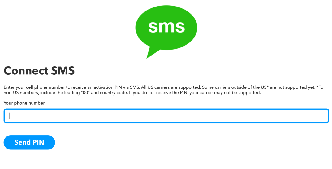
In case your phone number is not set, lets go to search:
And we click on settings and edit. Here you enter your phone number you wish to receive your text:
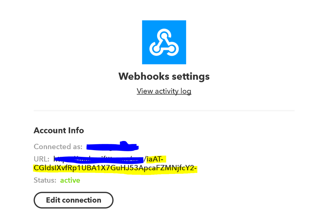
Now the last and most important part, we need to get your “mykey” needed to link ifttt with your esp8266.
We go to search again and this time type in webhooks. Then you go to settings and you copy the highlighted key into your ESP8266 sketch:
Now you are ready to continue to the sketch.
Here is the sketch for the ESP8266.
Original sketch was taken from this link and modified slightly for my project.
///////////////////////////////////////////////////////////////////////////////////////////////////

// Name: Steven Guzman

// Date: 12/13/2017

// Description: ESP8266 code for sending a message over to IFTTT that the garage door is open

///////////////////////////////////////////////////////////////////////////////////////////////////

#include <ESP8266WiFi.h>

#include <arduino.h>

#include <SPI.h>

#include "DataToMaker.h"

#define SERIAL_DEBUG // Uncomment this to dissable serial debugging

// Define program constants

const char* myKey = ""Enter your key right here"; // your maker key here

const char* ssid = "Enter your SSID wifi name here"; // your router ssid here

const char* password = "Enter your password here"; // your router password here

// declare new maker event with the name "ESP"

DataToMaker event(myKey, "Door");<span 				data-mce-type="bookmark" 				id="mce_SELREST_start" 				data-mce-style="overflow:hidden;line-height:0" 				style="overflow:hidden;line-height:0" 			></span>

// LEAVE SET

bool connectedToWiFI = false;

void setup()

{

#ifdef SERIAL_DEBUG

  Serial.begin(115200);

  delay(200);

  Serial.println();

#endif

  pinMode(2,INPUT);

  delay(10); // short delay

  WiFi.mode(WIFI_STA);

  ConnectWifi();

}

void loop() {

  if (wifiConnected)

  {

  debugln("connecting...");

    if (event.connect())

    {

       if (digitalRead(2) == HIGH)

      {

       event.setValue(1,"Garage Door is Open, close it NOW!!");

       debugln("Connected To Maker");

       event.post();

      }

      if (digitalRead(2) == LOW)

      {

        event.setValue(1,"Garage Door is Closed");

        debugln("Connect to Maker");

        event.post();

      }

    }

    else debugln("Failed To Connect To Maker!");

    delay(5000); // pause for 1 second

  }

  else

  {

    delay(60 * 1000); // 1 minute delay before trying to re connect

    ConnectWifi();

  }

}

bool ConnectWifi()

{

  // Connect to WiFi network

  debugln();

  debugln();

  debug("Connecting to ");

  debugln(ssid);

  unsigned long startTime = millis();

  WiFi.begin(ssid, password);

  while (WiFi.status() != WL_CONNECTED && startTime + 30 * 1000 >= millis()) {

    delay(500);

    debug(".");

  }

  if (WiFi.status() == WL_CONNECTED)

  {

    debugln("");

    debugln("WiFi connected");

  }

  else

  {

    WiFi.disconnect();

    debugln("");

    debugln("WiFi Timed Out!");

  }

}

bool wifiConnected()

{

  return WiFi.status() == WL_CONNECTED;

}

void debug(String message)

{

#ifdef SERIAL_DEBUG

  Serial.print(message);

#endif

}

void debugln(String message)

{

#ifdef SERIAL_DEBUG

  Serial.println(message);

#endif

}

void debugln()

{

#ifdef SERIAL_DEBUG

  Serial.println();

#endif

}
Here is the second file needed for the ESP8266:
#include <Arduino.h>

#include <ESP8266WiFi.h>

#ifndef DataToMaker_h

class DataToMaker

{

  public:

    DataToMaker(const char*, String); // constructor

    bool connect();

    bool setValue(int, String);

    void sendToMaker();

    void post();

  protected: // it is protected because the subclass needs access

    //to max distance!

  private:

    void compileData();

    WiFiClient client;

    const char* privateKey;

    String event;

    String value1, value2, value3 = "";

    bool dataAvailable;

    String postData;

};

DataToMaker::DataToMaker(const char* _privateKey, String _event)

{

  privateKey = _privateKey;

  event = _event;

}

bool DataToMaker::connect()

{

  if (client.connect("maker.ifttt.com", 80))

    return true;

  else return false;

}

void DataToMaker::post()

{

  compileData();

  client.print("POST /trigger/");

  client.print(event);

  client.print("/with/key/");

  client.print(privateKey);

  client.println(" HTTP/1.1");

  client.println("Host: maker.ifttt.com");

  client.println("User-Agent: Arduino/1.0");

  client.println("Connection: close");

  if (dataAvailable)

  { // append json values if available

    client.println("Content-Type: application/json");

    client.print("Content-Length: ");

    client.println(postData.length());

    client.println();

    client.println(postData);

  }

  else

    client.println();

}

bool DataToMaker::setValue(int valueToSet, String value)

{

  switch (valueToSet)

  {

    case 1:

      value1 = value;

      break;

    case 2:

      value2 = value;

      break;

    case 3:

      value3 = value;

      break;

    default:

      return false;

      break;

  }

  return true;

}

void DataToMaker::compileData()

{

  if (value1 != "" || value2 != "" || value3 != "")

  {

    dataAvailable = true;

    bool valueEntered = false;

    postData = "{";

    if (value1 != "")

    {

      postData.concat("\"value1\":\"");

      postData.concat(value1);

      valueEntered = true;

    }

    if (value2 != "")

    {

      if (valueEntered)postData.concat("\",");

      postData.concat("\"value2\":\"");

      postData.concat(value2);

      valueEntered = true;

    }

    if (value3 != "")

    {

      if (valueEntered)postData.concat("\",");

      postData.concat("\"value3\":\"");

      postData.concat(value3);

    }

    postData.concat("\"}");

  }

  else dataAvailable = false;

}

#endif<span 				data-mce-type="bookmark" 				id="mce_SELREST_start" 				data-mce-style="overflow:hidden;line-height:0" 				style="overflow:hidden;line-height:0" 			></span>
Make sure to place the datatomaker file code above in the same directory as the ESP8266 code.
FINAL THOUGHTS
Here is the final project assembled:
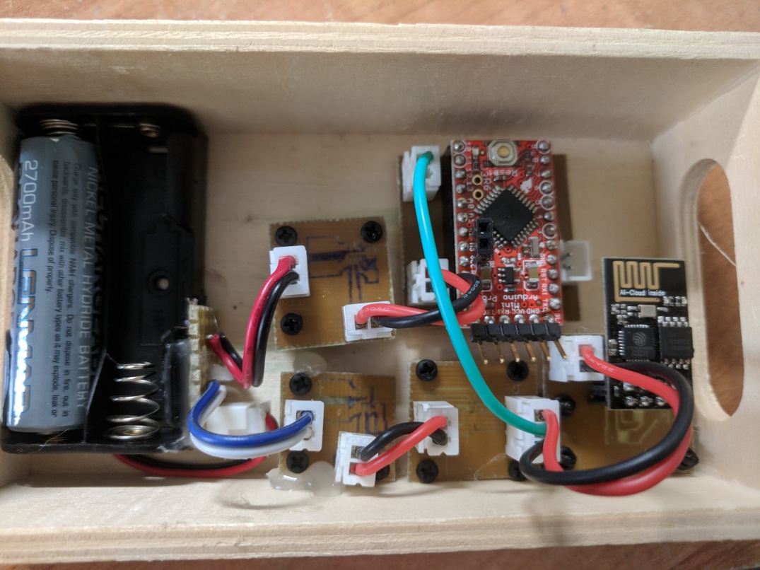
This project was not designed to be pretty but since I used my CNC machine to mill out the boards I was limited to the one side. There is an upside to designing it this way, if one or two of the boards happen to malfunction, you can switch it out. Or if you ever need to upgrade, you can easily swap out what you need to upgrade.
I’m planning on making a professional board and consolidating the boards into one or two boards in the future but for now I’m happy with the results.
If you have any questions please feel free to comment or if you find an error or an issue with anything posted please let me know and I’ll correct it.
THANK YOU!
