

INTRODUCTION
The arduino platform is one of the biggest and most popular platforms used for prototyping. One of the most popular Arduino boards is the Arduino Uno and for good reasons because its very intuitive and easy to use with plenty of IO pins and analog pins.
With the Arduino uno having 28-pins, sometimes your design or project will only require a handful of IO pins and will need to be crammed into a small board. That’s when the ATTINY85 IC comes to the rescue.
The ATTINY85 is a low-power, 8-bit AVR microcontroller. Its a great little micro controller that can be programmed with Arduino, though it does have its limitations like a smaller 8kB flash memory instead of the Arduino uno 32kB. Its is still a great alternative for small not so code intensive projects.
Along with having a small package, if you run this off battery you want to make sure it’ll last more than a couple of days. To fix this issue, we can implement a sleep cycle and wake it up using a watchdog timer that’ll make it last for easily over a year on 2 AA NiMh batteries. Below I’ll add the sleep code you can paste into your own to add a sleep function to your ATTiny85 projects.
BILL OF MATERIALS
HARDWARE/SCHEMATIC/CONNECTIONS
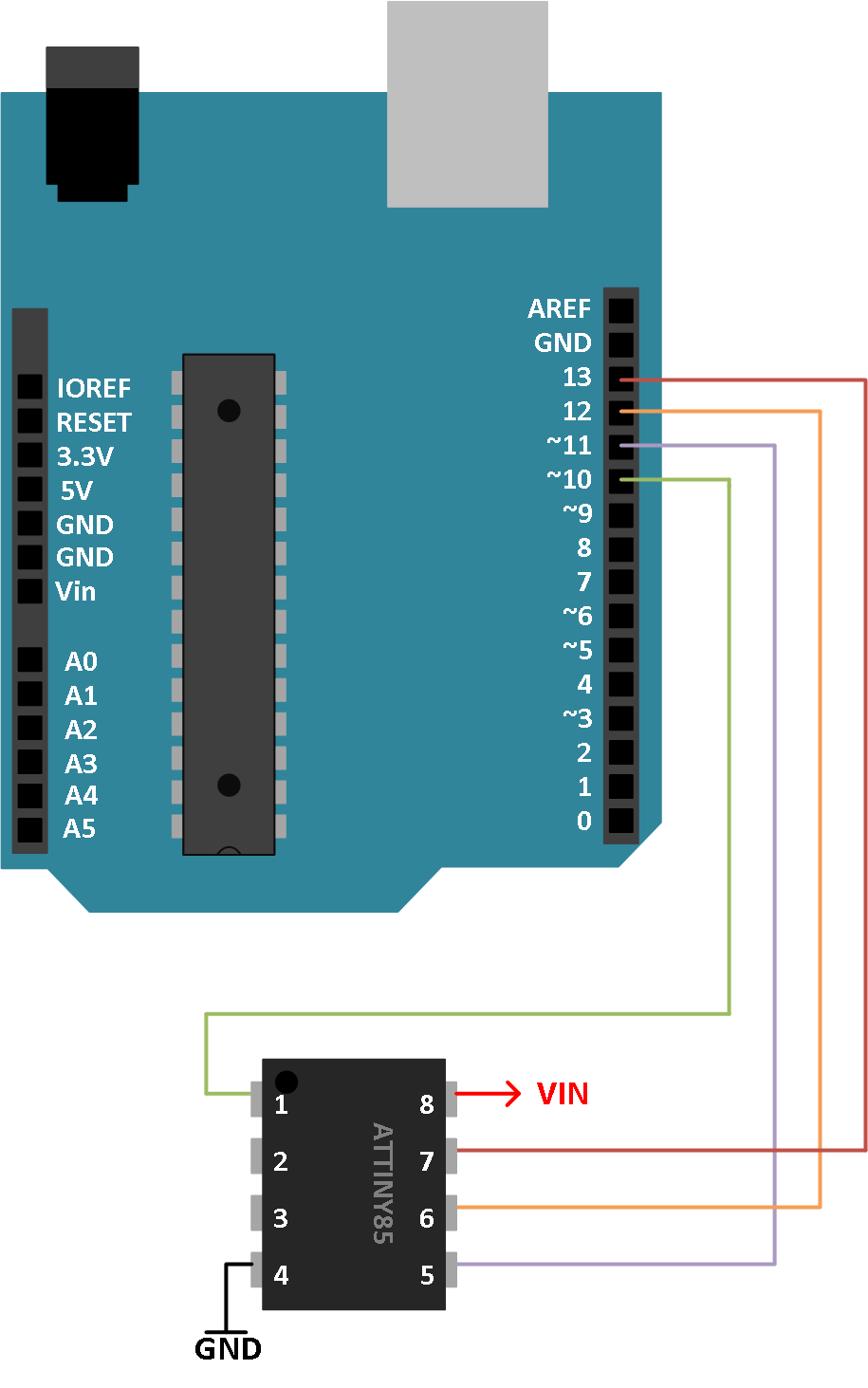
Below is a general wire diagram for connecting the Arduino Uno and the ATtiny85 in order to upload your program. Unlike the Atmega328P used on the arduino, the ATtiny85 does not require a special boot loader in order to upload Arduino code.
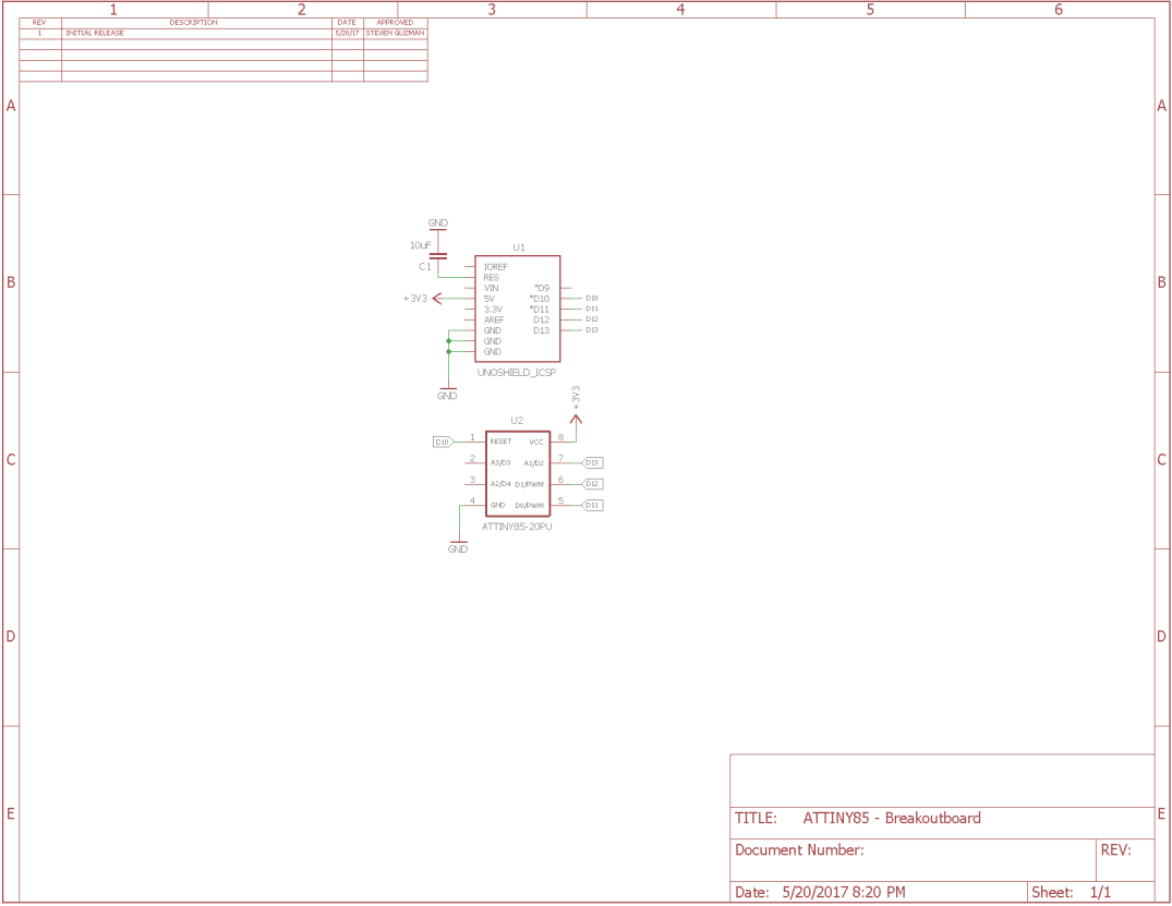
Here is a schematic version below:
SETUP
The next step is to download the libraries for the ATtiny85.
Go to file -> Preferences
Under Additional Boards Manager URLs copy and paste this link:
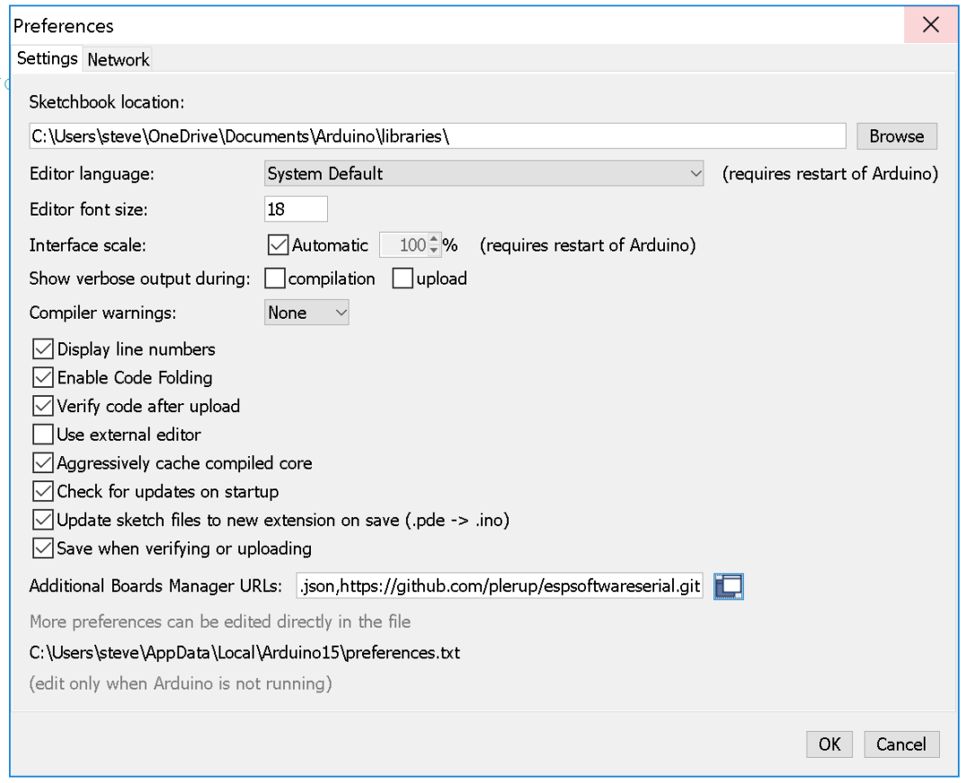
Then click ok.
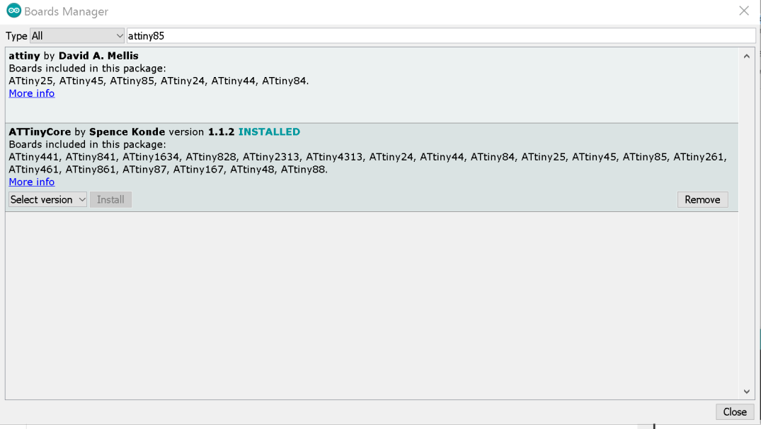
Next, go to tools -> Board -> Boards Manager
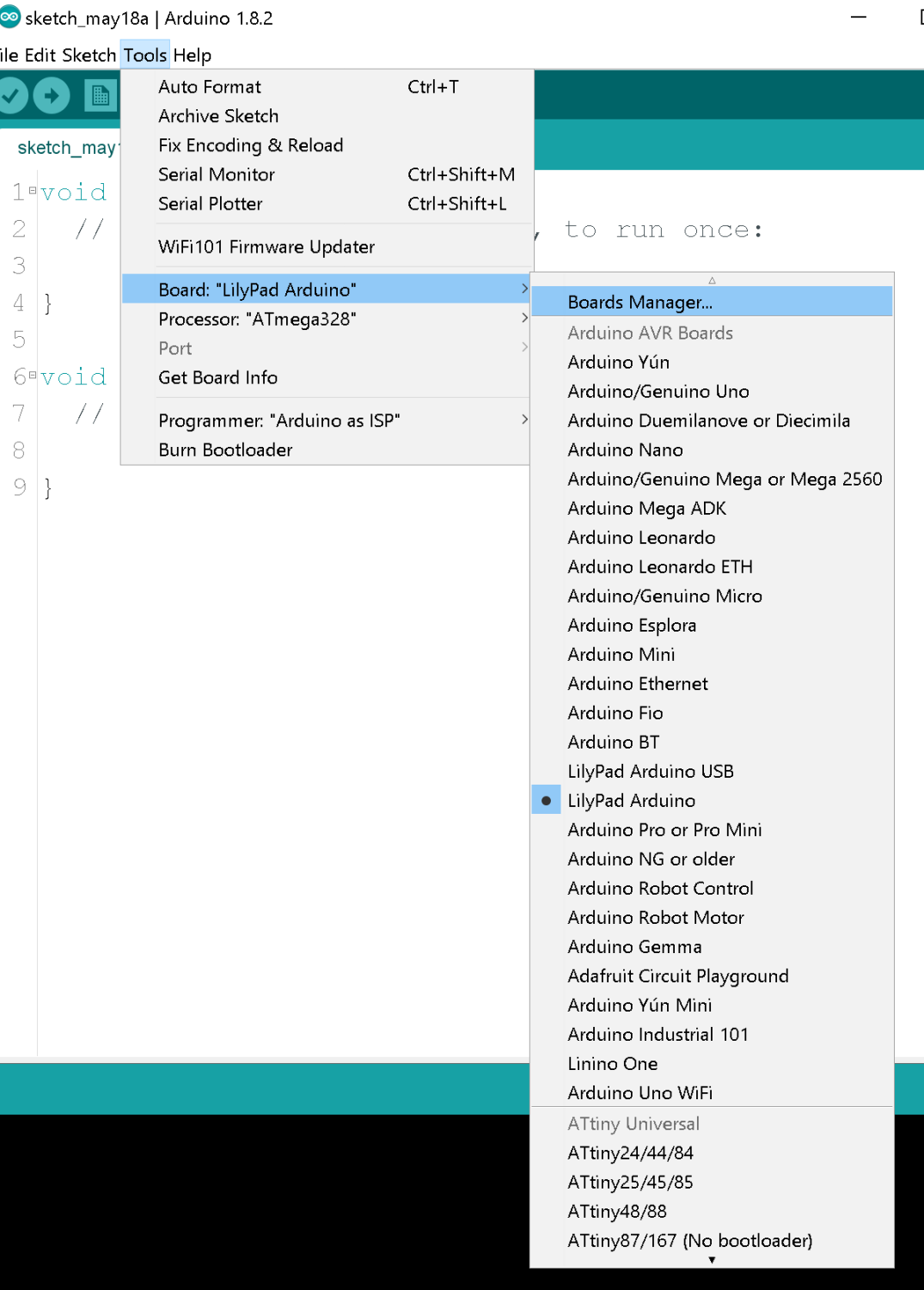
Next, type in ATtiny85 on the search bar and install the ATTinyCore by Spence Konde. Select the newest version available.
Now that you have the libraries installed for the ATTiny85 IC, you next need to setup your Arduino uno to be an ISP programmer to upload your code to the ATTiny85.
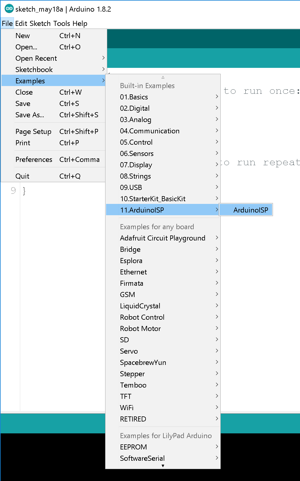
Once you’ve opened up that example code, you upload that sketch file into your arduino.
Next step is to choose the right board before uploading.
REMEMBER TO SELECT ARDUINO AS ISP UNDER PROGRAMMER or your code will not upload to the Attiny85.
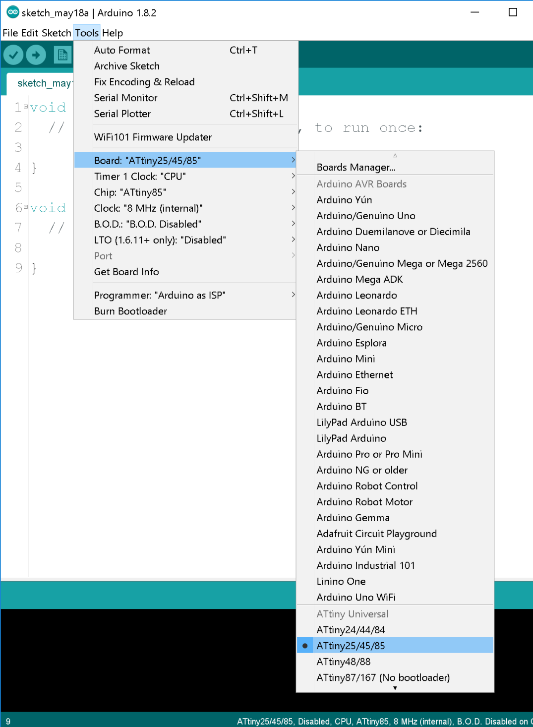
The last step before being able to upload your code to the ATTiny85 is to make sure your settings in the image above are exactly the same.
ATTINY85 SLEEP CODE
///////////////////////////////////////////////////////////////////////////////////////////
/// Title: Auto Garden Project (Tiny) //
/// Author: Steven Guzman //
/// Date: 5/11/17 //
/// Description: This code can be added to any ATTiny85 project in order to put it into //
/// a sleep cycle //
///////////////////////////////////////////////////////////////////////////////////////////
#include <avr/sleep.h>
#include <avr/wdt.h>
int watchdog_counter = 0; // Used for looping the watchdog timer
ISR(WDT_vect)
{
watchdog_counter++; // Increments the watchdog timer counter
}
void setup()
{
set_sleep_mode(SLEEP_MODE_PWR_DOWN); // Power down everything, will only wake up from WDT
sleep_enable(); // Enable sleep
}
void loop()
{
ADCSRA |= (1<<ADEN); // Turns on ADC in order to read analog values
// 15 = 2 minutes
// 37 = 5 minutes
// 75 = 10 minutes
// 112 = 15 minutes
// 255 = 30 minutes
// Loops the 8 second internal to extend the sleep state
while (watchdog_counter < 15)
{
setup_watchdog(9);
ADCSRA &= ~(1<<ADEN); // Turns off the ADC sleep_mode(); } watchdog_counter = 0; } // This is creating the back end code for running the sleep // function of the ATTiny85. The longest sleep cycle is // 8s //From: http://interface.khm.de/index.php/lab/experiments/sleep_watchdog_battery // 0=16ms, 1=32ms,2=64ms,3=128ms,4=250ms,5=500ms // 6=1 sec,7=2 sec, 8=4 sec, 9= 8sec void setup_watchdog(int ii) { byte bb; int ww; if (ii &gt; 9 ) ii=9;
bb=ii < 7;
if (ii > 7) bb|= (1<<5);
bb|= (1<<WDCE);
ww=bb;
MCUSR &= ~(1<<WDRF);
// start timed sequence
WDTCR |= (1<<WDCE) | (1<<WDE);
// set new watchdog timeout value
WDTCR = bb;
WDTCR |= _BV(WDIE);
}
For some reason the html code doesn’t properly convert the characters, I’ve attached the arduino file here.
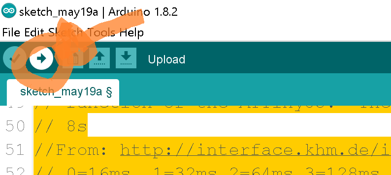
UPLOADING SKETCH
Now that you have the code ready. The next thing is to upload your code into the ATTiny85. Simply click on the right arrow in the tool bar and it’ll start uploading.
FINAL THOUGHTS
Hopefully this helped you guys learn how to easily use an ATTiny85 with your Arduino code. They are a little limited in what they can do but if your project is not that complicated and you need to save space then this is the micro controller for you.
Please leave me any comments below let me know what you think.
References
1. Microchip

Thnx for your contribution and insight, I was always using Atmega328p chips, but I think the attiny85 is less power hungry and more than suitable to do most jobs;-)
Unfortunately the code snippets are affected by HTML encoding (e.g. <avr/sleep.h>), could you correct them?
LikeLike
Hey Rik,
Thanks for the heads up, I was not aware that some of the characters were effected by the HTML encoding. I’ve attached a link right below the html box with the original arduino code. I had issues trying to correct the code in the HTML box. Hope this helps. Let me know if you need any help or if something still seems incorrect.
Thanks
LikeLike
This is perfect, thank you!
LikeLike
Hello Steven,
I have recently designed (with KiCAD) a programmer PCB that uses an Ardiono nano as ISP for programming ATtiny85s and another PCB for ATmega329P chips.
While reading this post, I noticed minor things that could be corrected :
– The right URL for the excellent Spence Konde ATtinycore is
http://drazzy.com/package_drazzy.com_index.json
I tried both Konde and Damellis cores. Konde allows to acces more features, and usually provides a more compact code.
– After loading the ArduinoISP sketch in the Arduino, one must connect a 10µF electrolytic capacitor between the GND and RST pins of the Arduino. That capacitor prevents the Arduino from being reprogrammed by the subsequent programs that one sends to the ISP.
– Concerning the bootloader, you are perfectly right to say that the ATtiny85 does not need a bootloader. By default the T85 is factory set to internal 1 MHz clock. If you want to choose a faster clock (8, 16 MHz internal) you have to select the clock in the tools menu and then use the command ‘Burn Bootloader’. This will set the internal ‘fuses’ of the tiny chip to use the chosen clock. Then afterwards you can upload the sketch.
Thank you for sharing your projects and your KiCAD files.
Philippe
LikeLike